

 CPS: Synergy: Smart Flexible Camera Sheet: Ultra-Thin Semantic-Guided Cooperative Micro-Camera Array
Objective

Develop a smart flexible sheet with a micro-camera array, wherein the cameras can individually or collectively target and track objects at different angles and distances.
Motivation
Existing camera systems either lack versatility in function or have a bulky form factor.
| Optical zoom | Adjustable Focus | Low light imaging | |
|---|---|---|---|
| Large Professional Cameras (e.g. DSLR's) | Yes | Yes | Excellent |
| Cell Phone Cameras | Yes (limited) | Poor | |
| Tiny cameras (e.g. in medical devices) | Cannot image without a high-intensity light source |
* High signal-to-noise ratio
* Optical Zoom
* Multiple planes of focus
* Face detection in modern cameras
* Understanding scenes from images and videos.
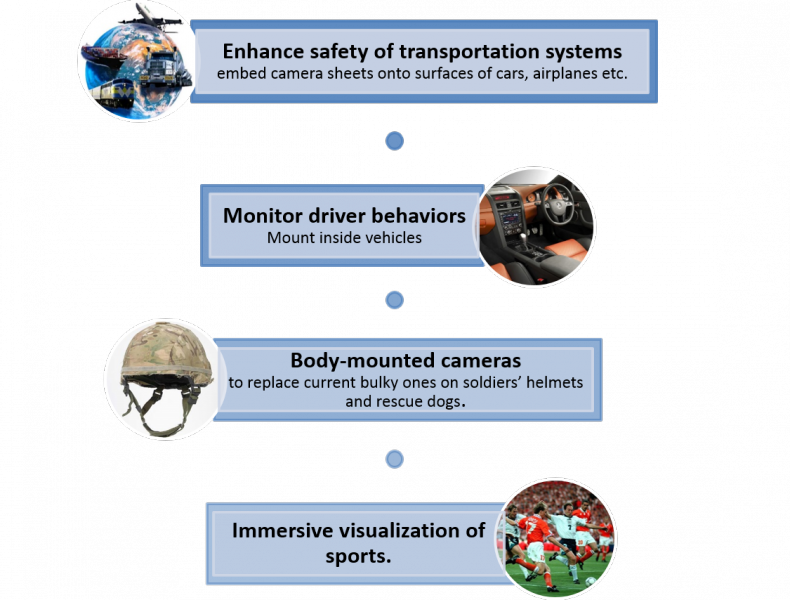
Targeted Applications
Implementation strategy (Hardware)
-
Fabrication of variable-focus lenses for the microcameras.
-
Develop light concentrators for enhanced collection and concentration of light to compensate for small lens apertures.
-
Design efficient micro-scale actuators for on-demand direction control of the cameras.
-
Realize the flexible camera sheet using batch fabrication techniques.
Implementation strategy (Software)
-
Develop efficient algorithms to combine noisy image data from multiple cameras into a single sharp image*.
-
Design new software to integrate the processes of depth estimation and object/scene recognition.
-
Use human-user interaction to train the new model for generic object/scene recognition with minimum supervision.
Project updates
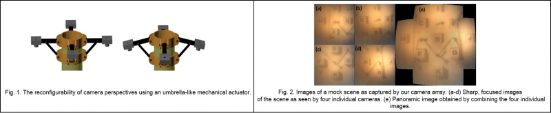
We report on our work on image processing for a multi-camera array. This part of our work was carried out in two steps: 1. Assembling a multi-camera array using a mechanical structure that enables control over the orientation of the cameras and hence the viewing direction. 2. Image processing to combine images from multiple cameras. We first assembled an array of multiple microcameras in such a way that it emulates two of the characteristics of our proposed flexible camera sheet - changeable viewing directions and tunable focus. The mechanical assembly design is modelled on the umbrella frame structure. The arms corresponding the umbrella ribs are used to support the microcameras. This design enables control over the orientation angle of the arms, similar to the opening and closing of an umbrella, and hence the viewing direction of the cameras. Also, each microcamera uses a tunable focus lens. This provides focusing and refocusing capabilities, similar to those of the proposed flexible camera sheet. For this experiment we used thermo-responsive hydrogel based tunable liquid lenses as a substitute for electrowetting based lenses, since we are still working on improving the electrowetting lens design for our system. We tested the implementation of our prototype microcamera array in a test scene. The test scene comprises of a periodic arrangement of 9 dice (1.5 cm x 1.5 cm x 1.5 cm) forming a rhombus (length = 16 cm). To simulate a realistic low-light surveillance environment, we placed the test scene in a dark box with a fiber optic light guide as the sole light source. The array was used to image the test scene at different viewing angles. Sharp images of all the sub scenes were obtained by individual cameras as seen in Fig. 2(a-d). As the first step towards combining images from different cameras, we used a commercial software, PTGuiTM to stitch these sub scenes into a single panoramic image as shown in Fig. 2(e). As seen from the figure, this yields to enhanced depth perception and a significantly large field of view of 1280, which is greater than that of any of the individual source images.
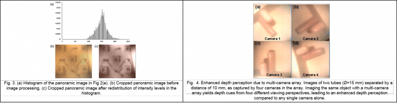
Next we attempted to improve the image quality of our combined image. Fig. 3. Shows a significantly improved image after processing and adjusting the intensity levels of the histogram of panorama in Fig. 2(e). To further demonstrate the enhancement in depth perception with our multi-camera array, we imaged a scene consisting of two cylindrical tubes placed one behind the other, separated by a distance of 10 mm. The scene was imaged with all four cameras in the array at an arbitrary angle. As can be seen in Fig. 4, while imaging the scene with a single camera, the depth-wise separation of different objects may (Fig 4(c) - (d)) or may not (Fig 4(a) - (b)) be apparent. However, while imaging with our multi-camera array, the same scene can be viewed from four different viewing perspectives thus leading to increased information about the relative positions of the two objects.
We are able to select the in-focus parts and preliminarily denoise the image. In implementation, due to the imperfection of disparity estimation, directly selecting a particular disparity value for a pixel could cause errors. Therefore, a patch-based averaging scheme is adopted to reduce the effect of imperfect disparity map. This is illustrated in Fig. 5 below. The reliability map indicates the average similarity of each pixel in the super image to the noisy target view. Larger value of R(x, y) implies larger difference between the super image and the target view at (x, y), and hence indicates low reliability for that pixel. By comparing the R(x, y) with a threshold, a binarized reliability map (lower right corner of Fig. 5) will be used for further enhancement of denoising using non-local patch matching.
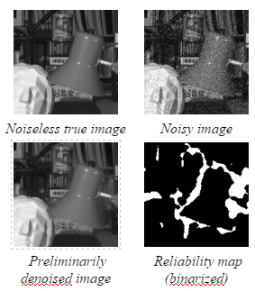
Fig. 5. Preliminary denoising and associated reliability map
Preliminary experimental results of the proposed algorithm are summarized here. We used four dataset from different database for our evaluation. For all datasets, white Gaussian noise with noise level s is added. In our experiments, we assume all datasets have maximum disparity of 15 between adjacent views. We evaluate the quality of denoising using peak signal-to-noise ratio (PSNR). We ran the algorithm on Intel(r) Core(tm) i7-4700MQ CPU (2.40GHz) and used MATLAB(r) to implement all the algorithms. For the efficiency of evaluation, "Knight", "Tarot", and "Truck" have been resized to 256x256, 256x256, and 400x300, respectively. "Ohta" remains unchanged and is of size 288x384. For subjective visual quality, we enlarge the images and select particular regions for comparison in Fig. 6 below. From the figure, we can observe that the proposed method shows great preservation of edges and textures, such as the whiteboard in "Ohta" and walls in "Knight", while both NLM and BM3D tend to smooth or blur these regions. As a result, both quantitative measurements and visual inspections reveal that our proposed method achieves great denoising quality compared to single view denoising algorithms.
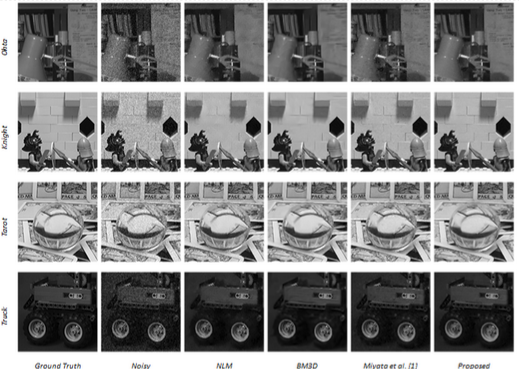
Fig. 6. Comparison between proposed denoising scheme, the method in [1], NLM, and BM3D (s = 20)
We have previously demonstrated individual liquid lenses actuated through electrowetting by utilizing area density modulated electrodes on rigid substrates [2]. This design has been translated into an array, fabricated of entirely flexible materials. Fig. 7 shows this array which has a PDMS substrate fabricated on a carrier wafer. Each lens in the 5x5 array can be independently turned by applying different voltages to the pad which corresponds with each lens. All lenses share a common ground.
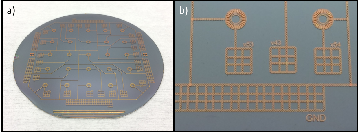
Figure 7. a) Patterned 5x5 array of electrowetting lenses on flexible substrate (and carrier wafer). b) A close up of two lenses in the array showing the electrode structure and the contacting pads for applying voltage.
We have also begun testing with an array of single millimeter-scale fixed cameras. Here, we create a 3x3 array of these small cameras embedded in a flexible sheet of PDMS. This was achieved by first utilizing stereolithography to fabricate a rigid array of camera holders configured in a 10mm grid. The resulting flexible camera sheet can acquire images while adhered to a planer surface, or the camera sheet can be wrapped around a convex shape, such as a cylinder. Fig. 8 shows the set up and configuration of the camera sheet, and Fig. 9 shows the images acquired from the set up and stitched into a single, cohesive image.
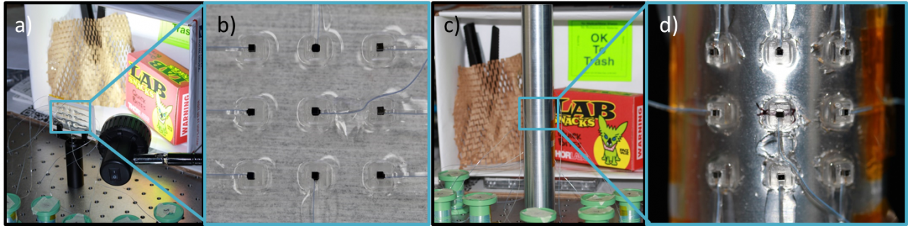
Figure 8. a) Setup for acquiring images from the nine camera planer array, highlighted by the blue box. b) A close up of the camera array on a flat surface. c) Setup for acquiring images from the camera array wrapped on an aluminum cylinder. d) A close up of the camera array wrapped on the convex surface to increase field of view.
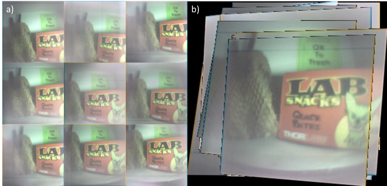
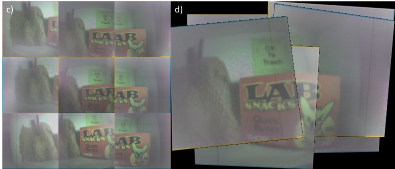
Figure 9. Compiled images of the camera array in planar (a-b) and convex (c-d) configurations. a) Nine individual images acquired from 9 cameras of the array on a flat, planer surface, as show in Fig 2b. b) The nine images in (a) stitched together into a single image. c) Nine individual images acquired from cameras on convex array as shown in Fig. 2d. d) Six of these images in (c) stitch into a single image. Note that the borders corresponding to individual images are shown here for presentation only; they can be chosen not shown.
In addition to the progress of hardware design, we also developed algorithm, called 3D focus image stacks, for functional emulations of single camera operations using a multicamera array. A 3D focus image stack is a 3D matrix consisting of all pixels from all cameras aligned against the image coordinates of a reference image for a given disparity value d. Each disparity value d corresponds to the focal plane at the depth associated with d, and if an object is on that plane, the corresponding pixel will appear clear in the multi-focus image, as Fig. 10 shows.
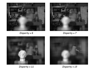
Figure 10. Illustration of multi-focus images at different disparity values (depths).
Publications
References
[1] M. Miyata, K. Kodama, and T. Hamamoto. "Fast multiple-view denoising based on image reconstruction by plane sweeping." in Proc. IEEE Vis. Commun. Image Process., Dec. 2014, pp. 462-465.
[2] A. O. Ashtiani, and H. Jiang, "Design and fabrication of an electrohydrodynamically
actuated microlens with areal density modulated electrodes" in Journal of Micromechanics and
Microengineering, 26(1), 015004, 2015.